My cat has a lengthy history of bringing me "gifts."
Cat owners quickly discover that cats do this. However,
Cosmo was especially prolific and would bring gifts of the
four-legged scurrying variety, almost always at night and often
still very much scurrying.
Her record is four rats in one night, all live.
Dead rodents are unpleasant; still-scurrying are much worse.
They take up residence in your house unless you finish the job that she didn't!
And take up residence they did.
I picked up a package of biscuits in the kitchen one day,
and a rat jumped out!
Yes, true story.
This was unacceptable, but the solution was simple:
don't have a cat bad kitties lose their indoor-outdoor priveleges at night!
And lest you think perhaps the rats found a way in on their own, what's that in her mouth?!
Apparently, it got away from her on her first ascent of the ramps.
Yes. I have plenty of video evidence like this.
Some context
My basement is technically a cellar because it is only
accessible from outside the house.
That is, no interior door (suitable for people) connects the main living space
to the basement.
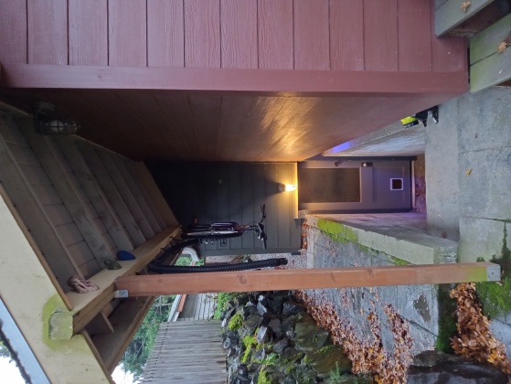
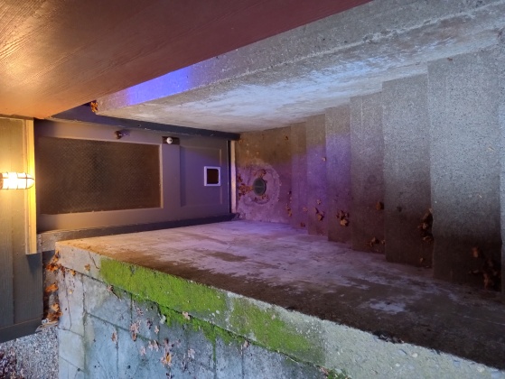
The cellar door is outside in the back of the house
and down a covered stairwell.
Notice the cat flap in the cellar door?
Cat infrastructure
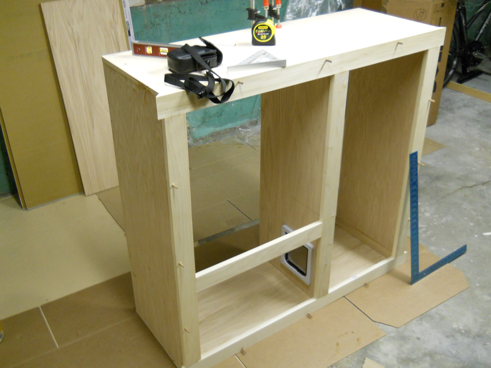
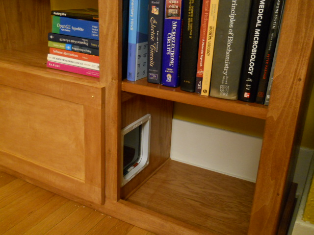
Cosmo does have a direct route from the main floor to the
cellar: her own personal, semi-secret door built into a bookcase leading
to a series of ramps to the cellar floor.
I built it when I was younger and had (more of) the misguided priorities of youth.
I did have some defensible motivations, though.
I did need more shelf space, and I wanted to avoid:
a litterbox in the house and everything that goes with that, and
putting a cat flap in my front or back house doors.
Apparently, I was less troubled by the prospect of cutting a hole in the living room floor...
Back to Cosmo
The solution was simple: keep her from reentering the main floor of the
house at night by making the cat flap in the bookcase one-way.
I had anticipated this might be necessary even before the rat situation
and installed a
Cat Mate 4-Way-Locking Cat Flap.
(I bought mine over a decade ago, but they don't appear to have changed.)
The "locks" allow you to theoretically make the door one-way, but
all they actually do is control which direction(s) the flap can
be pushed.
I would set the bookshelf flap to be "one-way" outbound in the
evening, and Cosmo could leave the house and come and go from the cellar
but not reenter the main floor.
Theoretically...
An off-the-shelf solution that wasn't
It worked briefly, but Felis catus isn't stupid.
Cosmo quickly learned that she could still enter by pulling the
flap, usually making a house-waking racket because her first few attempts
would fail, and the flap would bang down on the frame and be amplified by the
acoustics of the wooden bookcase it's built into.
Ok, fine. We'll just evict her lure her outside with food and
physically block that hole in the floor, so she absolutely can not reenter
the house at night but can still come and go from the cellar.
(Don't worry: she has a plush setup in the cellar.)
Incidentally, the Cat Mate flaps are great, really well built, and I
would recommend them with the caveat that whether or not the "one-way"
feature works depends on your cat's IQ.
Years pass
Being an elderly cat now, she is never eager to leave her living room
bed in the evening.
Even food does not necessarily lure her out.
And now we have a new reason to keep her out: she seems to need
to announce her return when she reenters.
She yowls...loudly.
Yes, every time she reenters.
Yes, multiple times at night.
I think the technical term is caterwauling.
I would rather let her stay inside until she is ready to leave on her own.
If she stayed inside (and quiet!), that's fine, too.
But she won't.
She's a cat—that is, nocturnal.
Her "litterbox" is the entire outside world, and there is still hunting to do...
The best solution is clear, but it's too late: don't have pets.
Sorry, son. I do like cats, but when Cosmo ceases to
voom we're done.
Right now I need a genuine one-way door,
a cat valve.
It looks like I have another project...
The road not taken
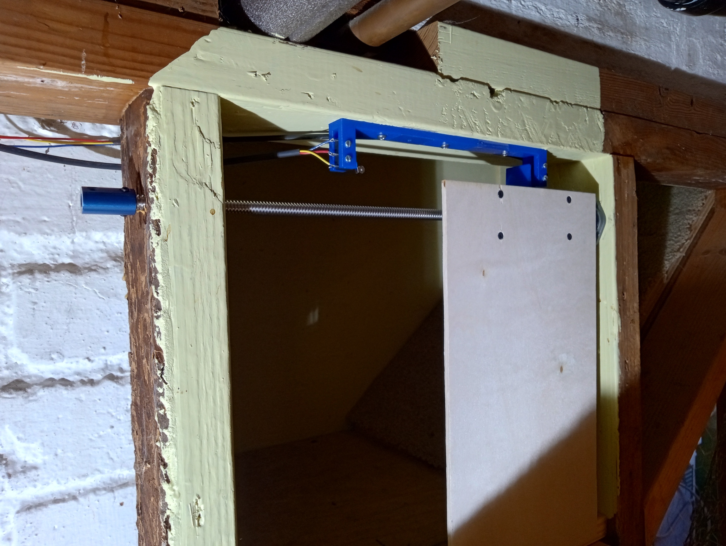
I have a place to control her access to the house:
the top landing of her kitty ramps.
And it's convenient since it's entirely out of the way
of our living space. (...meaning, whatever I build, it has no aesthetic requirements.)
The future home of a sliding door.
I can imagine an improved, strictly mechanical and entirely passive, cat
flap which actually
latches when it closes that could be mounted in that portal on the top
landing of her ramps (between those 2x4's).
It would require some sort of (manual) arming mechanism since I only want
the locking to occur at night.
I believe such a mechanism could probably be printed on my
FlashForge, too.
This would hypothetically solve my cat-shaped problem with minimal complexity,
"hypothetically" because mechanical mechanisms can be finicky and would have
to remain robust against kitty rage.
And I said I can imagine, not that I've done the design work.
Lingering doubt about the feasibility of a strictly passive mechanism
and the lure of opening and closing her door at the touch of a button
led me to take the other road: active control.
Scoping requirements
I didn't put a lot of thought into the actual door/barrier design.
The 34cm wide x 30cm high space allowed for a ≤17cm sliding panel to
cover a ≤15cm opening with 1cm overlap, and this seemed both simplest
and probably most reliable.
A panel sliding behind (on the interior side of) a fixed wall
arguably gives kitty the least "attack surface" for her prying claws,
a serious merit that would not apply to any conventional hinged door.
I committed early to a sliding door design.
Whatever the drive mechanism a
reversible motor and associated electrical drive circuitry
is required to move that panel back and forth.
Since the goal is automatically closing the door when the cat
exits, sensing/detecting/inferring the cat's exit is necessary.
Obviously, something needs to integrate all the above, sensors
and actuators, so at least a microcontroller and firmware will be involved.
Design
So pet-management-motivated sub-projects include at least:
mechanical design for a panel driven by some sort of linear motion actuator
Plenty of
other options do exist, but I think we can rule out hydraulic in this case. 😏
Rack and pinion struck me as requiring more precision than one should strive for
in a plywood and 2x4 context.
Directly coupling a (gear reduced) motor to a screw is trivial, so I went
with the dangerous option, dangerous because a door driven by a lead-screw,
even with a small-ish 12V motor, can exert enough force on an obstacle to
constitute a kitty guillotine!
Ultimately, the door only moves ≈1cm/s, so I'm sure she'll get out
of the way, but I'm not going to risk finding two halves of my cat.
This will motivate a proximity sensor, so I'll be paying for the mechanical
simplicity of a directly-driven lead-screw actuator with a bit more
complexity in the electronics and software.
Engineering tradeoffs!
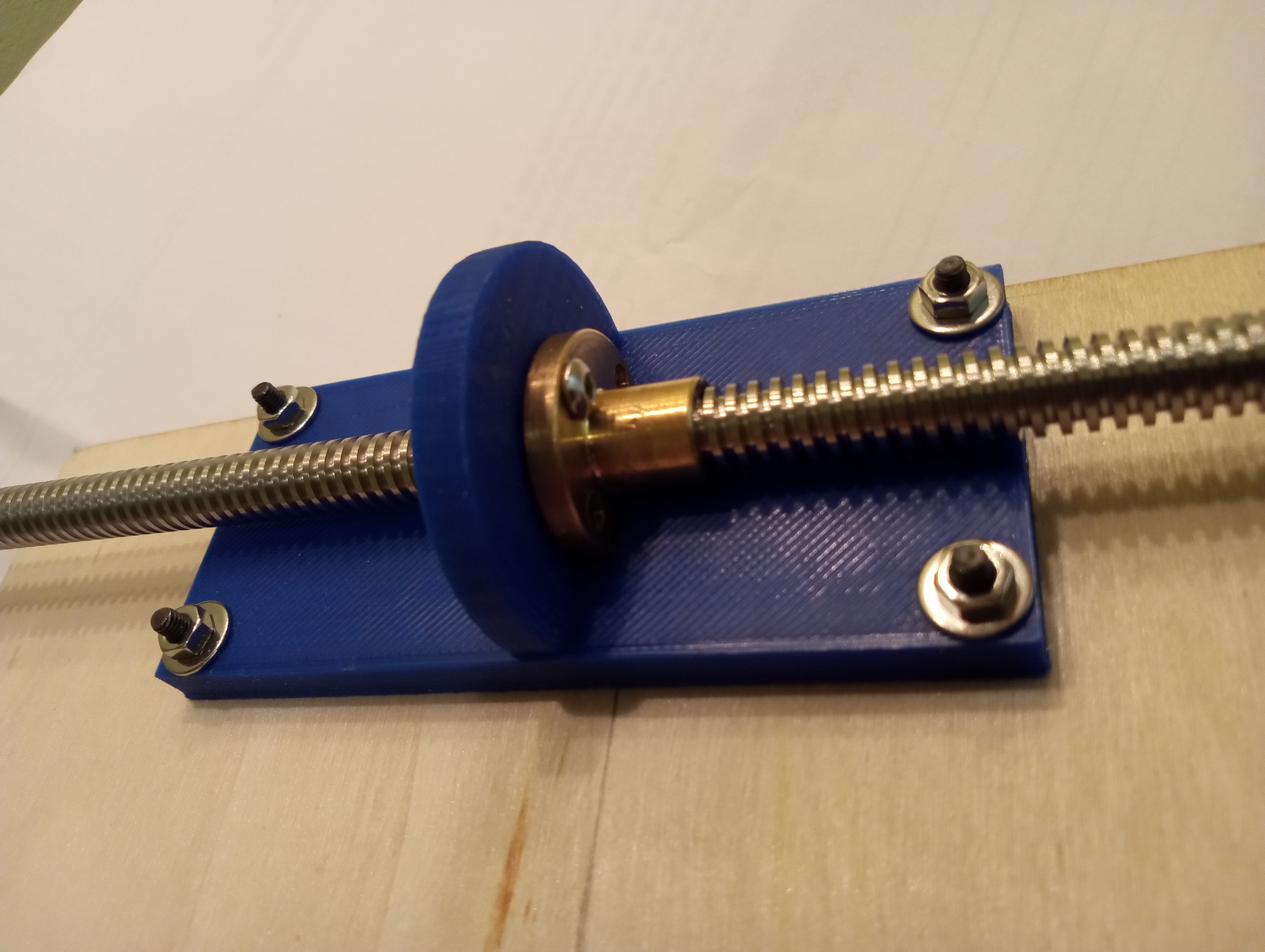
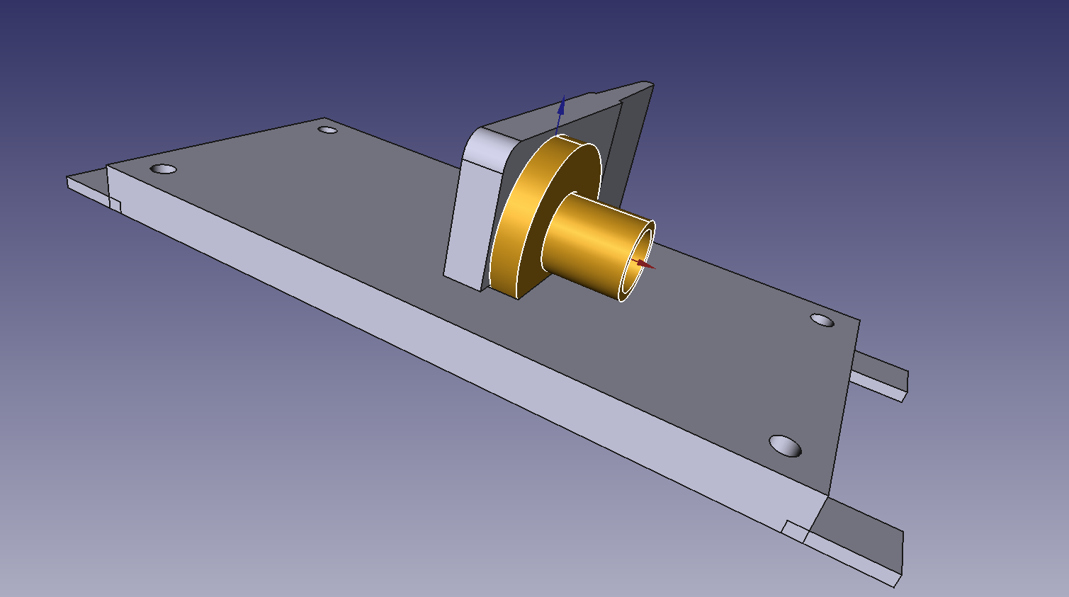
The door hangs from the lead screw by a nut mounted in this 3D-printed
fixture.
Above is an early print before I recognized the fixture should include
a tab to press the limit switches seen below.
The door (2mm birch plywood) simply hangs from this, so it take very
little force and, thus, a very light-duty motor, to move it.
The motor's shaft will fit in the coupler (blue cylinder) on the
left and drive the lead-screw directly.
The other end of the lead-screw is carried by a flange-block bearing,
just the edge of which is visible behind the door.
Control
Two options also exist for the control of the door's movement (and, in fact,
for control of anything):
open-loop
and
closed-loop.
Optimistic control ≠ optimal control
Closed-loop is usually optimistic, and optimistic control isn't even
engineering.
Closed loop control relies on a model which in this case is simply
the easily-calculated (or measured) relationship between motor speed and
door travel. By simply powering the motor for an appropriate period of
time the door would be moved a predictable distance...predictable
but not necessarily precise.
Electrical fluctuations could result in small deviations each time the
door is opened or closed.
If the deviations were centrally and symmetrically
distributed—they need not be normally distributed but
probably are—they would cancel each other out over time, so the
door would remain within safe operating bounds.
Alternatively, biases in the control circuits, software, or physics of
the motor, could cause the door's left and right "rest" positions to
shift.
Essentially, with open-loop control the controller (whatever it is)
never really "knows" exactly where the door is.
Closed-loop
If you look inside your 3D printer you will likely see not only a lead-screw
carrying something (probably the print bed), but
limit switches at
either end of something's range of travel...a very simple way to achieve
positive—that is, closed-loop— control.
I used SPDT
switches in which the unpressed position closes the corresponding motor control
input and the pressed position closes a circuit into GPIO.
This way as soon as the door hits it's limiting position:
power is physically cutoff to the motor and
a logical signal is received in the microcontroller indicating
the limiting position has been reached.
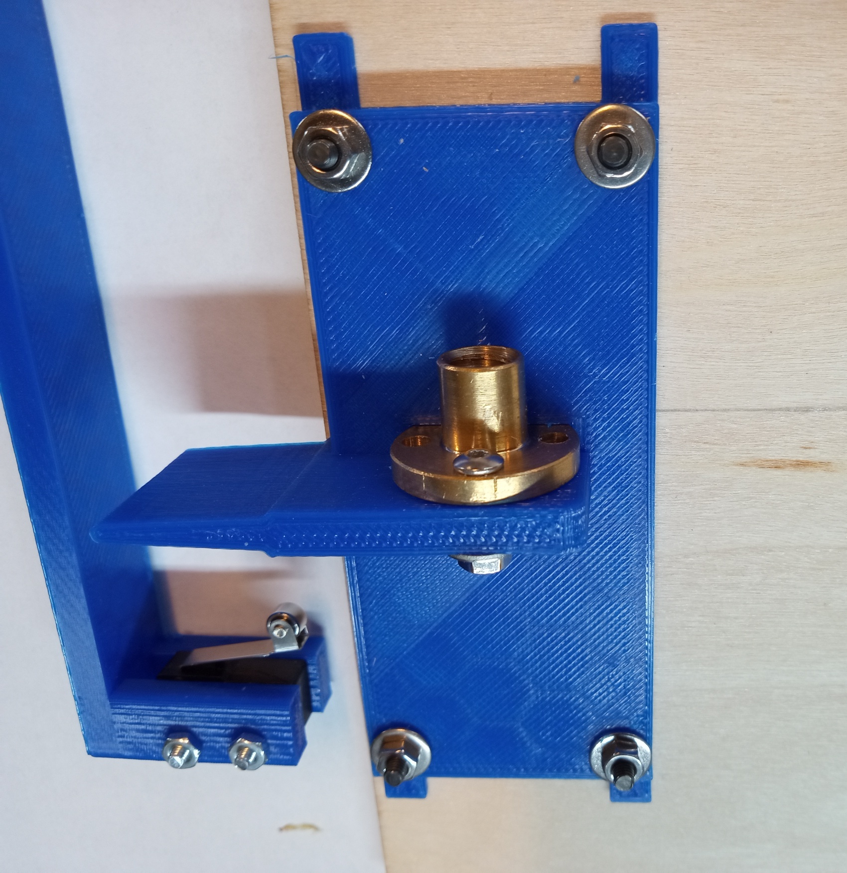
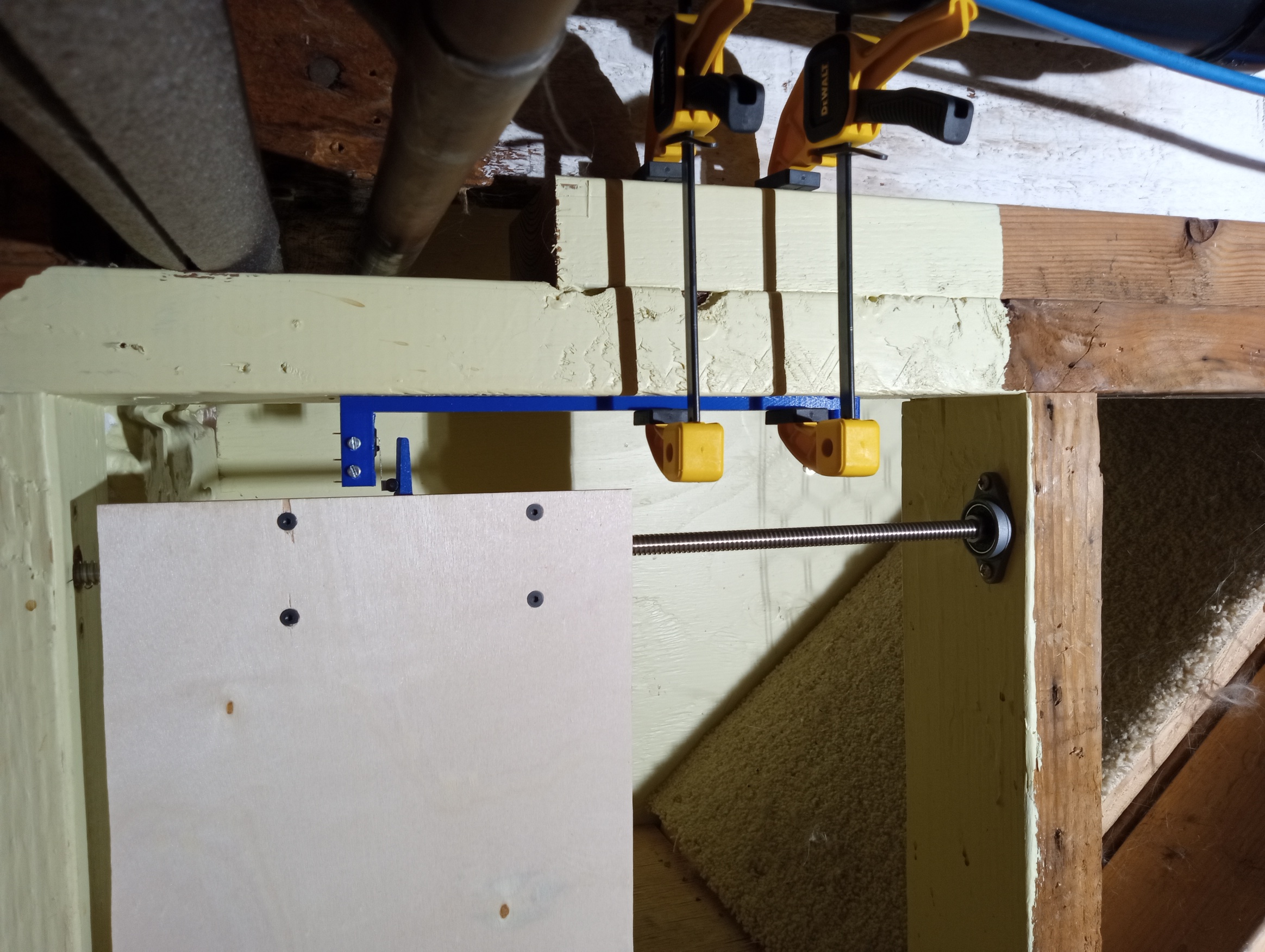
A tab on top of the nut fixture presses the switches at either side.
The vertical tab hits limit switches to limit the door's linear travel,
shown above prior to installation.
Test fitting (with clamps) the position of the limit switch mount.
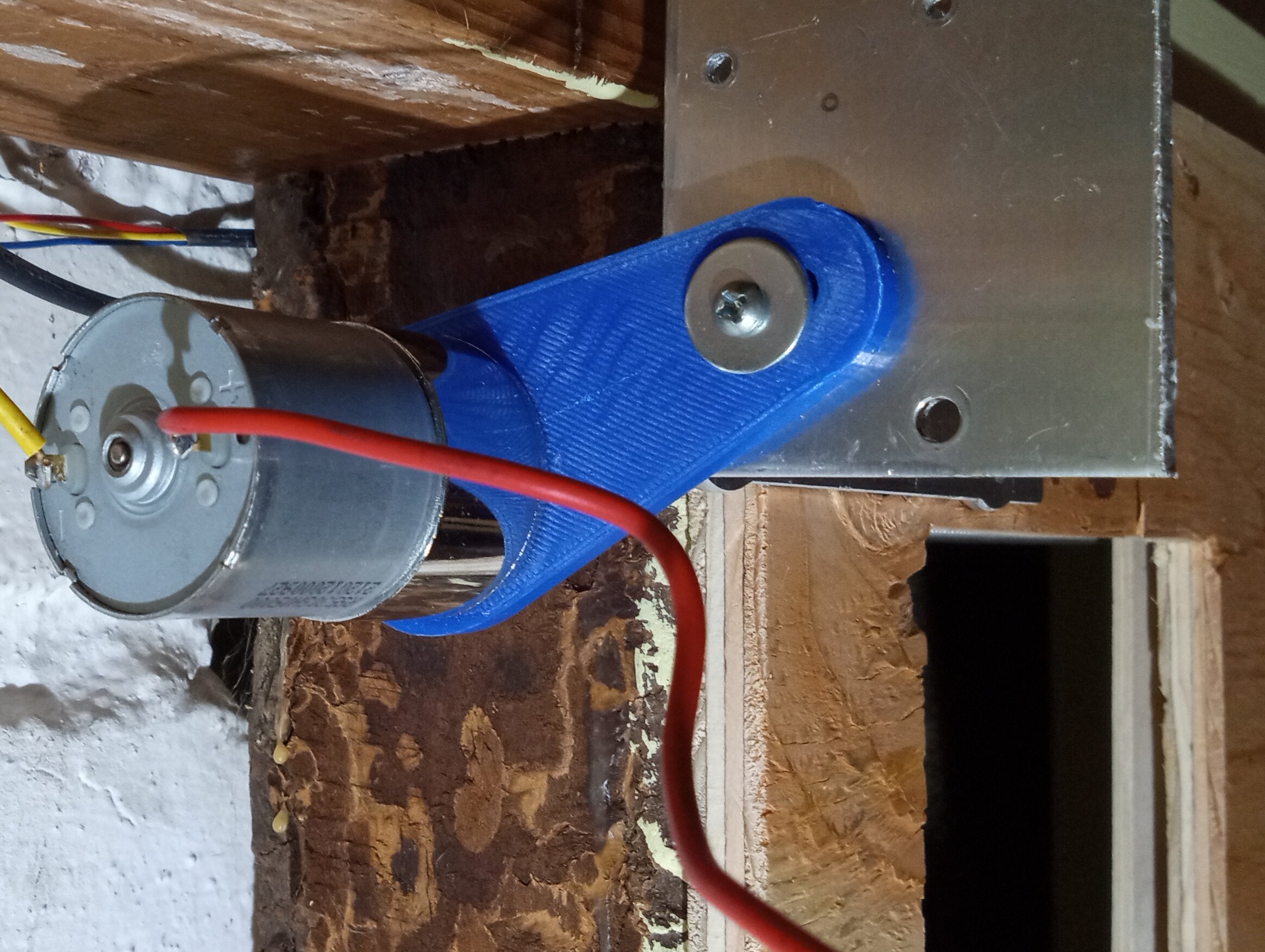
Motor mount
And here's the reason I favored a lead-screw approach:
no little precision required.
A
Greartisan DC 12V 300RPM
motor drives the lead screw directly.
That chunk of right-angled aluminum to which the motor mount is attached?
It's the dashboard mount for a car stereo salvaged from an old Chrysler.
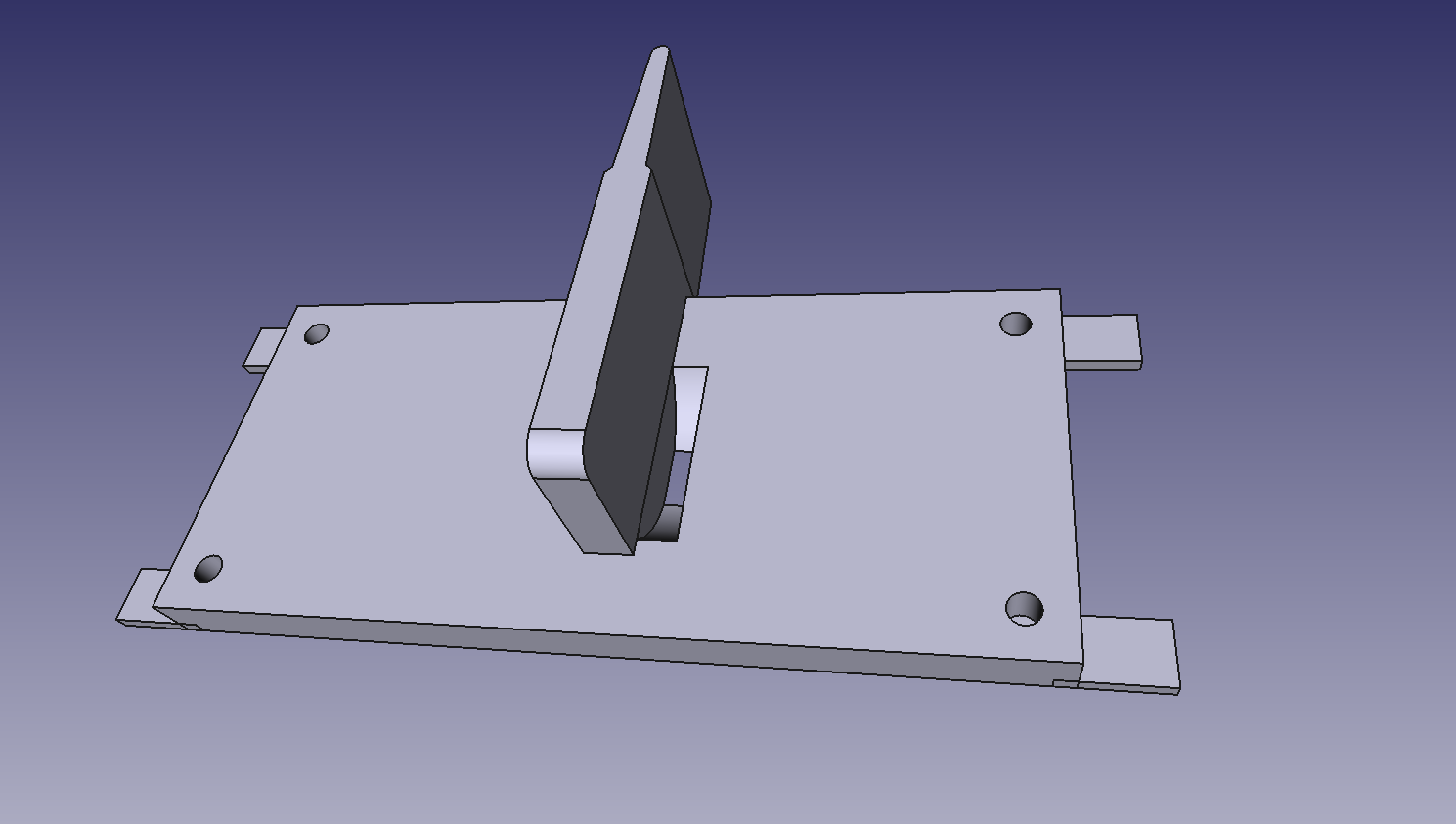
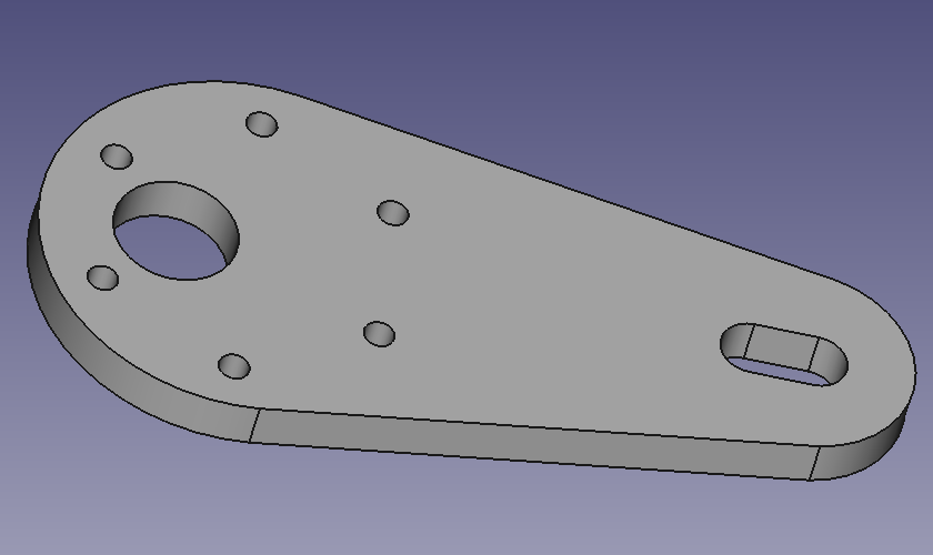
CAD for an adjustable motor mount.
The motor mount provides 2 dimensions of freedom, rotational and radial,
thanks to that oval hole, so
the whole assembly can be loosely installed (some parts clamped into place),
find it's own optimal position then screwed/bolted into that position.
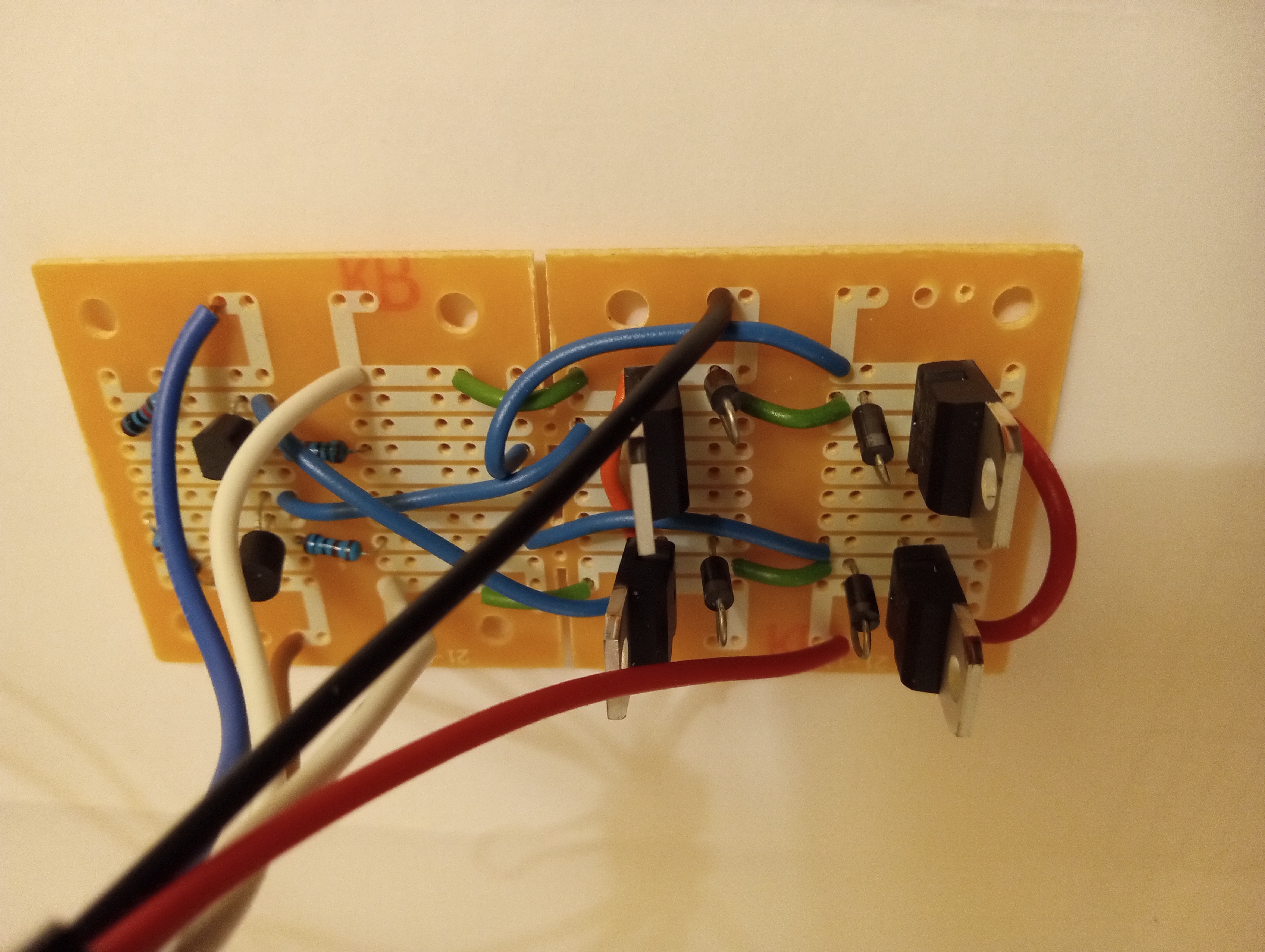
Electronics
Reversibly driving a motor entail an H-bridge,
and I don't have much to add to Wikipedia's summary.
Yes, I could have used any number of motor driver ICs, but to stay in touch with my
discrete component roots, I overbuilt one with Darlington pair BJTs.
...and good I did, because a hiccup in final wiring got those TIP12x's
hotter than an IC would have withstood. 🤦
An H-bridge translates
GPIO signals from the Raspberry Pi to the power levels and current directions required by the motor.
Those are TIP120 and TIP125's Darlington pairs, not MOSFETs.
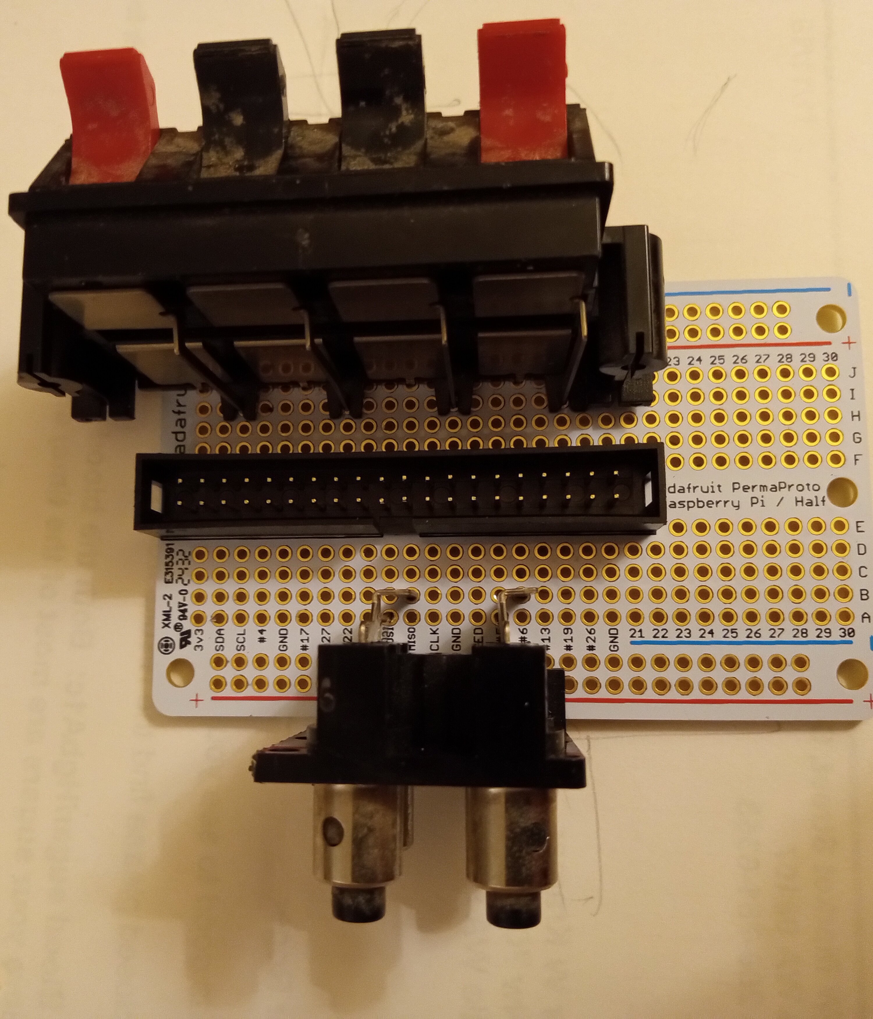
...and speaking of salvage, above are speaker and antenna connector
blocks from an old receiver my son and I disassembled.
With a little coercion they fit the hole spacing of an Adafruit prototyping board.
This is how the Raspberry Pi 4 is connected to motor, sensors and power.
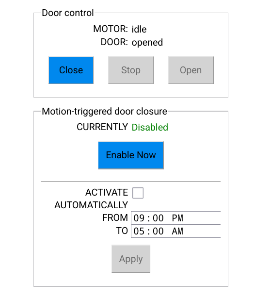
Software
I said I wanted "button" control of the door, but of course it's 2024
and "button" means virtual button on a screen.
And I not only need to be able to command the door to open and close,
I probably need to edit control parameters for its automatic capabilities.
In other words, I need at least some UI.
With a little software work, the phone in your pocket is a universal
remote control like no other.
This also loosely implies microprocessor rather than microcontroller.
A phone screenshot of the HTML UI...the whole UI.
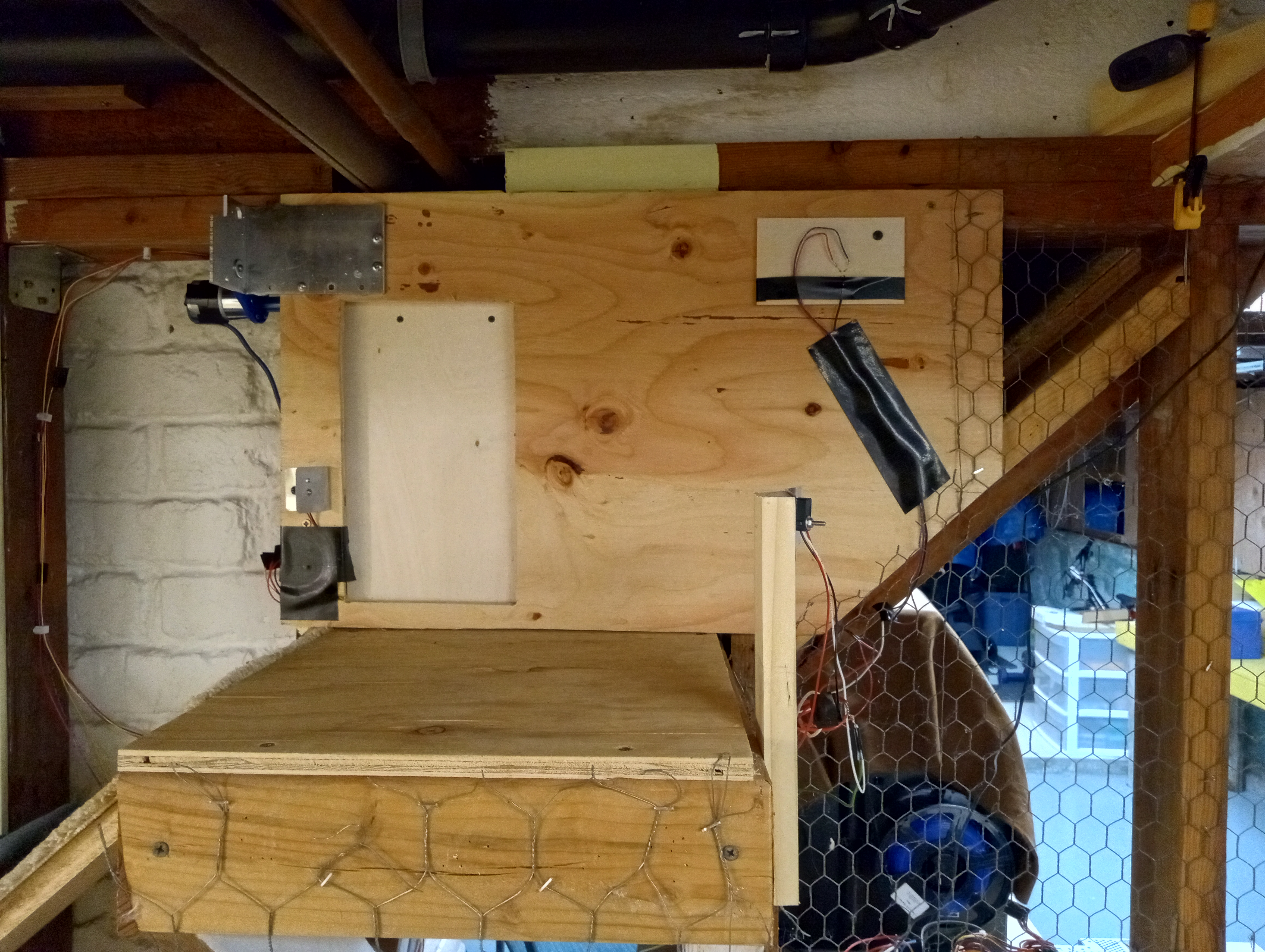
The finished installation (with the door closed).
Notice the IR emitter/detector pair, the emitter mounted just left of the door
and the detector on the post on the right side of the platform.
The beam crosses the top landing diagonally to insure she can't be up there
without breaking it!
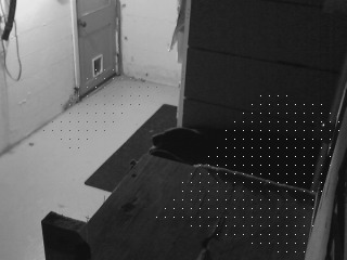
An old Logitech C270 webcam currently clamped in place (top right corner of picture)
watches the vicinity of the basement door (below).
The webcam's view with motion-detection regions overlayed.
Motion in the red region triggers door closure; motion in the
green region is merely logged.
The dots in the right image are the pixels actually involved in
correlation computations.
Exit detection
Proximity detection
Integration
Software was implemented as two daemons: catvalve and camomon.
catvalve
manages all the GPIO to the motor and sensors
listens for signals from camomon, and
provides a barest of bare-bones HTTP server for the UI.
camomon
Camomon (for CAt MOtion MONitor) monitors video from a webcam.
When it detects motion (in specific regions), it signals catvalve
("signals" in the Unix IPC sense with
"kill").
If "Motion-triggered door closure" is enabled within catvalve,
receipt of that signal closes the door.
In more detail,
camomon grabs still images from the webcam at ≈10Hz.
It's a color webcam, of course, but camomon only uses
the luminance of the YUYV output.
A lack of correlation between corresponding pixels in successive still
images indicates probable motion.
For efficiency, it only uses a sparse subset of pixels within
specified polygonal regions of its field of view in the correlation
computations.
The subsets are those pixels that lie at the intersections of a configurable
grid.
Camomon also saves the images containing motion.
Importantly, camomon is entirely independent of catvalve
and could be repurposed.
Finally, because I only want automatic door closure at night I use cron
to launch camomon (rather than adding to it's code something
a standard utility already exists to do!).
Only motion in the red polygon (above) triggers the
signal to catvalve (and thus door closure), because I want to
insure Cosmo is as far as possible from the "guillotine" when it closes.
Motion is detected in the green polygon, too, but only images are saved
for that motion; no signals are sent.
This was primarily to verify that the IR beam break sensors positioned
diagonally across the platform in front of the door were reliably
detecting her presence—that is, video footage should agree with
IR beam-break sensor logs.
You "wrote an HTTP server?!"
Ill-advised as that might sound, I would argue it's far easier (and more generalizable)
than e.g. developing an Android/iOS app speaking some other network protocol.
HTTP is simple and when requirements are severely constrained writing an
HTTP server is also simple.
For example, it only accepts one connection because it's only for use on the household LAN.
And it only need parse a couple URL encoded parameters to trigger GPIO signals
to run the motor.
And, no, I'm not bloody installing Apache (or Nginx or any other enterprise
grade server) to serve exactly one webpage.
And I only need my C compiler, not the 250MB Android Studio.
I could go on...
Updates (2026)
Sadly, this project's inspiration, Cosmo, is no more.
She did what cats often do: went out one night and didn't return.